The KNX standard


NK-iGLASS-6 è una tastiera in vetro KNX con tecnologia capacitiva disponibile di colore bianco o nero, è adatta per essere alloggiata in una scatola da incasso 503 ed integra un modulo a 6 ingressi digitali normalmente aperti e 6 uscite led.
Oltre ad essere dotata di feedback acustico, la tastiera, mediante opportuna programmazione, permette ad ogni singolo pulsante di essere illuminato individualmente.
È possibile inoltre attivare una retroilluminazione diffusa di tutti i pulsanti, sia continua che temporanea, la quale genera anche un alone di luce che si propaga sulla parete.
Dimensions: Housing for 503 wall box
Power supply: From KNX bus 21..30 Vcc SELV current consumption < 10mA
General characteristics:
• 6 configurable inputs
• 6 configurable feedback LED (embedded)
• Configurable backlighting
• Configurable acoustic feedback


NK-iGLASS-4 is a KNX glass keyboard with capacitive technology available in black or white color and is suitable to be housed in a 503 wall box.
It integrates a 4 digital inputs module to normally open, 4 feedback LEDs and anacoustic buzzer, all fully programmable.
It is also possible to activate a diffuse backlighting of all the buttons, either continuous or temporary, which also generates a light halo on the wall.
Dimensions: Housing for 503 wall box
Power supply: From KNX bus 21..30 Vcc SELV current consumption < 10mA
General characteristics:
• 4 configurable inputs
• 4 configurable feedback LED (embedded)
• Configurable backlighting
• Configurable acoustic feedback

The power supply unit NK-PS160 provides the system power necessary for the instabus EIB.
The connection to the bus line is established by clicking the device onto the DIN-rail (with a data rail installed) and/or via the bus connection block located on the front side.
The integrated choke prevents the data telegrams from short-circuiting on the bus line. When the built-in reset switch is operated, the bus devices are returned to their initial state.
Dimensions: 4 modules for DIN rail
Input voltage: Rate voltage: from 100V to 240V AC 50..60Hz
Output voltage: 29 DC +-1V
Output current: Max 160 mA (short circuit protection)
Control elements: 1 built-in reset switch for output power supply
Indicators:
1 Led green (presence of bus voltage)
1 Led red (overload)

The power supply unit NK-PS320 provides the system power necessary for the instabus EIB.
The connection to the bus line is established by clicking the device onto the DIN-rail (with a data rail installed) and/or via the bus connection block located on the front side.
The integrated choke prevents the data telegrams from short-circuiting on the bus line. When the built-in reset switch is operated, the bus devices are returned to their initial state.
Dimensions: 4 modules for DIN rail
Input voltage: Rate voltage: from 100V to 240V AC 50..60Hz
Output voltage: 29 DC +-1V
Output current: Max 320 mA (short circuit protection)
Control elements: 1 built-in reset switch for output power supply
Indicators:
1 Led green (presence of bus voltage)
1 Led red (overload)

The power supply unit NK-PS640 provides the system power necessary for the instabus EIB.
The connection to the bus line is established by clicking the device onto the DIN-rail (with a data rail installed) and/or via the bus connection block located on the front side.
The integrated choke prevents the data telegrams from short-circuiting on the bus line. When the built-in reset switch is operated, the bus devices are returned to their initial state.
Dimensions: 6 modules for DIN rail
Input voltage: Rate voltage: from 100V to 240V AC 50..60Hz
Output voltage: 29 DC +-1V
Output current: Max 640 mA (short circuit protection)
Control elements: 1 built-in reset switch for output power supply
Indicators:
1 Led green (presence of bus voltage)
1 Led red (overload)


NK-IO32M is equipped with KNX communication interface and includes:
• 2 digital inputs
• 1 analog input
• 2 relay output (bistable)
Digital inputs are intended to be connected to free potential contacts and can interface sensors, traditional buttons, etc; they can be used to on/off commands, dimming, shutter control, scene recall and control, sequences of 3 objects.
Analog input, can manage one temperature probe (with On/Off threshold) or one thermostats to control heating and cooling equipments, valves, 2 and 4 pipes fan coils; etc.. Analog input, alternatively to the temperature sensor, can manage a Infrared Receiver (IRX) in order to forward to the bus up to 8 channel coming from a Infrared Remote Control (IRC) with on/off commands, scenes, sequences of 2 objects, dimmer and shutter. Outputs include switching function with timed delays, staircase function, scene recall, lock or logic function.
The 2 outputs can be configured:
• Each output can be configured independently to control generic loads (2 independent channels)
• Each output can be configured independently for ON / OFF or continuous switching (PWM) for Electric valves (solenoid actuators) (2 independent channels)
• Outputs can be configured in pairs for the management of roller shutters and blinds; (1 channel).
Dimensions: height x diameter: 52 x 28mm
Power supply: From KNX bus 21..30 Vcc SELV current consumption < 10mA
Digital inputs:
• For potential free contacts
• MAX cable length ≤ 20m (twisted)
• Voltage scanning Vn = 3,3V (internally generated)
Analog input:
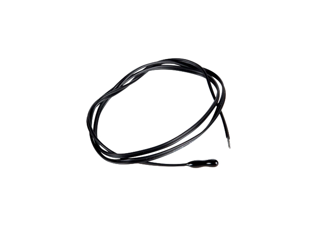
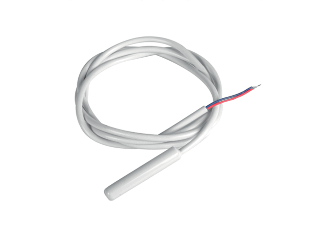
Connection to temperature Probe:
NK-SDT1 (range from -20°C to +100°C)
NK-SDT2 (range from -50°C to +60°C)
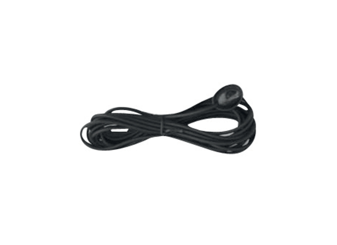
Connection to infrared receiver: NK-RIR
Outputs:
• 10 A cos φ 1 - 230 Vac
• Max capacitance at 230V: 21μF 5.000 cycles
• Max load incandescent lamps: 1500W 50.000 cycles
• Max load fluorescent lamps: 6 x18W 25.000 cycles
•Max load halogen lamps: 500W 50.000 cycles
•Max load gas discharge lamps: 200W 25.000 cycles


NK-IO44M is dedicated to interfacing free potential contacts through the 4 input channels, for example sensors, traditional buttons, etc. and 4 output channels at low voltage for drive LED for synoptics panels or switches.
Dimensions: height x width x depth: 43x36x17mm
Power supply: From KNX bus 21..30 Vcc SELV current consumption < 10mA
Digital inputs:
•4 digital inputs for potential free contacts
•MAX cable lenght 10m (twisted)
•Voltage scanning Vn = 3,3V (internally generated)
Digital LED outputs:
4 low voltage outputs for signal LEDS
Max 0,5 mA for each output


NK-IO84M module includes 4 digital inputs to interface free potential contacts; 4 analog / digital inputs for free potential contacts or temperature sensors and 4 LED outputs.
Digital inputs can interface sensors, traditional buttons, etc; 4 LED output channels at low voltage can drive LED for synoptics panels or switches.
Dimensions: height x width x depth: 43x36x24mm
Power supply: From KNX bus 21..30 Vcc SELV current consumption < 10mA
12 configurable channels:
• [01 ÷ 04] 4 digital inputs (for free potential contacts)
[05 ÷ 08] 4 digital or analogic inputs (for free potential contacts or temperature probe)
• [09 ÷ 12] 4 low voltage outputs for signal LEDS
Digital inputs:
• 8 channels [01 ÷ 08] for free potential contacts
• Voltage scanning 3,3 V Dc
• MAX inputs cable lenght 30m (twisted) [01 ÷ 04]
• MAX inputs cable lenght 10m (twisted) [05 ÷ 08]
• 6 poles terminal with screws [05 ÷ 08]
Analog inputs:
• 4 channels [05 ÷ 08] configurable as temperatur sensors with
both probes:
NK-SDT1 (range from -20°C to +100°C)
NK-SDT2 (range from -50°C to +60°C)
• 2 channels [05 ÷ 06] configurable as thermostat
Digital LED outputs: 4 low voltage outputs for signal LEDS
Max 0,3 mA for each output
Heating and cooling mode:
• Mode can be set with HVAC MODE object or with set point
• Set point change is programmable via BUS
• 2 ON/OFF points and algorithm for PWM control
• 3 speed fan coil control
• OFF MODE for open windows (contacts required)
• Comfort MODE (occupied room)


The DIN RAIL 8 Input / 8 Output Module NK-IO88 is a KNX DIN rail mounting device useful to interface commands (e.g. push buttons) or loads (e.g. lamps) for any kind of applications. The device is equipped with 8 binary inputs (potential free) and 8 binary relay outputs. Inputs can be connected to conventional switching devices, e.g. push buttons, switches, floating contacts, for switching functions with pulse edge evaluation (e.g. rising or falling edge, toggle...).
Inputs can be configured with ETS SW, as output to drive LEDS. Inputs can be used to for on/off commands, dimming, shutter control, scene recall and control; outputs include switching function, scene recall and control logic function.
The 8 outputs on board can be configured:
• Each output can be configured independently for load control (R1 to R8)
• Each output can be configured independently for ON / OFF or continuous switching (PWM) for Electric valves (solenoid actuators) (EV1 to EV8)
• Outputs can be configured in pairs for the management of roller shutters and blinds; up to 4 channels (Channels A to D)
• Outputs can be configured in pairs for management of Motor Reductor or for solenoid valves with 3-point control or for ventilating grille; up to 4 channels (Channels A to D)
• Fan Coil Actuator for 2/4 pipes systems for Heating / Cooling with 3 speed motors) (uses relay from 1 to 5)
Dimensions: Standard 4M for DIN rail mount
Power supply: From KNX bus 21..30 Vcc SELV current consumption < 10mA
Connections:
• Outputs: 2 screw connection for each input, MAX cable width. 4 mm2
• Inputs: 3 screw connection every 2 inputs, MAX cable width. 4 mm2
General characteristics:
• 8 inputs for free potential contacts configurable also as low voltage outputs for signal LEDS
• 8 relay outputs (16 A)
Outputs:
• Resistive loads: Max 16 A
• Incandescent lamps: Max 10 A
• Motor and motor reduction unites: Max 10 A
• Fluorescent lamps with electronic transformer: Max 6 A (max 140uF) max 3A (700W)


The DIN RAIL 4 Input / 4 Output Module NK-IO44 is a KNX DIN rail mounting device useful to interface commands (e.g. push buttons) or loads (e.g. lamps) for any kind of applications. The device is equipped with 4 binary inputs (potential free) and 4 binary relay outputs.
Inputs can be connected to conventional switching devices, e.g. push buttons, switches, floating contacts, for switching functions with pulse edge evaluation (e.g. rising or falling edge, toggle...).
Inputs can be configured with ETS SW, as output to drive LEDS. Inputs can be used to for on/off commands, dimming, shutter control, scene recall and control; outputs include switching function, scene recall and control logic function.
The 4 outputs on board can be configured:
• Each output can be configured independently for load control (R1 to R4)
• Each output can be configured independently for ON / OFF or continuous switching (PWM) for Electric valves (solenoid actuators) (EV1 to EV4)
• Outputs can be configured in pairs for the management of roller shutters and blinds; up to 2 channels (Channels A to B)
• Outputs can be configured in pairs for management of Motor Reductor or for solenoid valves with 3-point control or for ventilating grille; up to 2 channels (Channels A to B)
Dimensions: Standard 4M for DIN rail mount
Power supply: From KNX bus 21..30 Vcc SELV current consumption < 10mA
Connections:
• Outputs: 2 screw connection for each input, MAX cable width. 4 mm2
• Inputs: 3 screw connection every 2 inputs, MAX cable width. 4 mm2
General characteristics:
• 4 inputs for free potential contacts configurable also as low voltage outputs for signal LEDS
• 4 relay outputs (16 A)
Outputs:
• Resistive loads: Max 16 A
• Incandescent lamps: Max 10 A
• Motor and motor reduction unites: Max 10 A
• Fluorescent lamps with electronic transformer: Max 6 A
• Fluorescent lamps (max 140uF): Max 3 A (700W)


The DIN RAIL 4 output Module NK-M4U is a KNX DIN rail mounting device useful to interface commands (e.g. push buttons) or loads (e.g. lamps) for any kind of applications.
The 4 outputs on board can be configured:
• Each output can be configured independently for load control
• Each output can be configured independently for ON/OFF or continuous switching (PWM) for Electric valves
• Outputs can be configured in pairs for the management of roller shutters and blinds; up to 2 channels (Channels A to B)
• Outputs can be configured in pairs for management of Motor Reductor with 3 point control or for electronic valves or ventilating grille; up to 2 channels (Channels A to B)
Dimensions: Standard 4M for DIN rail mount
Power supply: From KNX bus 21..30 Vcc SELV current consumption < 10mA
Connections: Outputs: 2 screw connection for each input, MAX cable width. 4 mm2
General characteristics: 4 relay outputs (16 A)
Outputs:
• Resistive loads: Max 16 A
• Incandescent lamps: Max 10 A
• Motor and motor reduction unites: Max 10 A
• Fluorescent lamps with electronic transformer: Max 4 A
• Fluorescent lamps (max 140uF): Max 3 A (700W)


The DIN RAIL 8 output Module NK-M8U is a KNX DIN rail mounting device useful to interface commands (e.g. push buttons) or loads (e.g. lamps) for any kind of applications.
The 8 outputs on board can be configured:
• Each output can be configured independently for load control (R1 to R8)
• Each output can be configured independently for ON/OFF or continuous switching (PWM) for Electric valves (solenoid actuators) (EV1 to EV8)
• Outputs can be configured in pairs for the management of roller shutters and blinds; up to 4 channels (Channels A to D)
• Outputs can be configured in pairs for management of Motor Reductor or for solenoid valves with 3 point control or for ventilating grille; up to 4 channels (Channels A to D)
• Fan Coil Actuator for 2/4 pipes systems for Heating / Cooling with 3 speed motors) (uses relay from 1 to 5)
Dimensions: Standard 4M for DIN rail mount
Power supply: From KNX bus 21..30 Vcc SELV current consumption < 10mA
Connections: Outputs: 2 screw connection for each input, MAX cable width. 4 mm2
General characteristics: 8 relay outputs (16 A)
Outputs:
• Resistive loads: Max 16 A
• Incandescent lamps: Max 10 A
• Motor and motor reduction unites: Max 10 A
• Fluorescent lamps with electronic transformer: Max 4 A
• Fluorescent lamps (max 140uF): Max 3 A (700W)


NK-M12U is a Din Rail 12 output 16 A actuator and each output is associated to a frontal button configured to switch the relay witch logical interlock.
The 12 outputs on board can be configured:
• Control up to 12 independent loads / lights
• Control up to 6 independent blind / roller shutters with mechanical end position
Dimensions: Standard 9M for DIN rail mount
Power supply: From KNX bus 21..30 Vcc SELV current consumption < 10mA
Connections: Outputs: 2 screw connection for each input, MAX cable width. 4 mm2
General characteristics: 12 relay outputs (16 A)
Outputs:
• Resistive loads: Max 16 A
• Incandescent lamps: Max 10 A
• Motor and motor reduction unites: Max 10 A
• Fluorescent lamps with electronic transformer (max 140uF): Max 3A (700W)